- About MAA
- Membership
- MAA Publications
- Periodicals
- Blogs
- MAA Book Series
- MAA Press (an imprint of the AMS)
- MAA Notes
- MAA Reviews
- Mathematical Communication
- Information for Libraries
- Author Resources
- Advertise with MAA
- Meetings
- Competitions
- Programs
- Communities
- MAA Sections
- SIGMAA
- MAA Connect
- Students
- MAA Awards
- Awards Booklets
- Writing Awards
- Teaching Awards
- Service Awards
- Research Awards
- Lecture Awards
- Putnam Competition Individual and Team Winners
- D. E. Shaw Group AMC 8 Awards & Certificates
- Maryam Mirzakhani AMC 10 A Awards & Certificates
- Two Sigma AMC 10 B Awards & Certificates
- Jane Street AMC 12 A Awards & Certificates
- Akamai AMC 12 B Awards & Certificates
- High School Teachers
- News
You are here
The Theorem that Won the War: Part 1.2 – The Enigma Encryption
To encrypt a message, an Enigma operator typed it into a keyboard. When a key was pressed, an electrical signal would pass through a plugboard \(S\); through a sequence of rotors \(R_{1}\), \(R_{2}\), \(R_{3}\); then through a reflector \(Q\) that would send the signal back through the rotors in the reverse order, and then through the plugboard, lighting up the encrypted version of the letter. We can represent this process as encrypting the original plaintext letter \(p\) as the encrypted ciphertext letter \(c\).
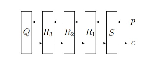
Figure 6. Diagram of Enigma encryption process,
beginning with the plaintext letter \(p\) and ending with the ciphertext letter \(c\).
To create the paper Enigma, you’ll need to cut out a set of encryption rotors; a template appears here. For convenience and tractability, we’ll omit the plugboard and use just a single rotor and the reflector; we’ll also reduce our alphabet to six letters \(a\), \(b\), \(c\), \(d\), \(e\), \(f\). These omissions do not substantially alter the process used by the Poles to break Enigma.
Our paper Enigma will require two types of rotors: a “keyboard” rotor and a “reflector” rotor. To prepare a keyboard rotor, draw one-way arrows from one vertex to another. Each vertex should have a unique “outgoing” arrow and a unique “incoming” arrow. Figure 7 below shows some “forbidden” setups and one allowable one. (Note that while you can do a “return” path so that two vertices are connected to each other, it’s discouraged because it’s less interesting.)
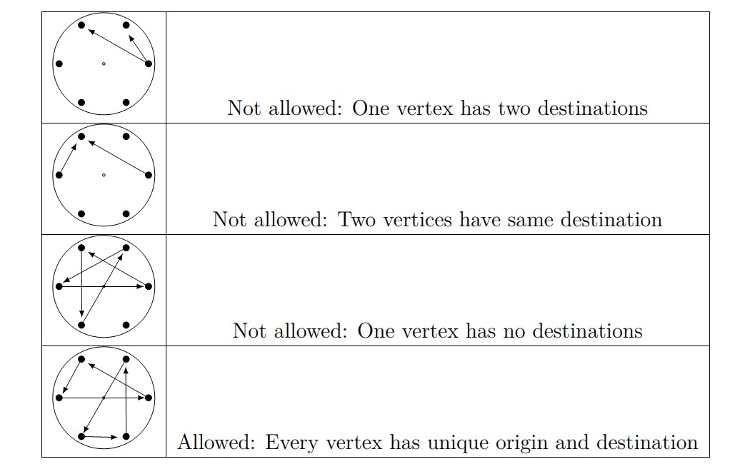
Figure 7. Diagrams of various allowable and forbidden “keyboard” rotors.
The reflector rotor is constructed in almost the same way, but this time our arrows are bidirectional and simply join vertices. Again, every vertex must have one and only one connection. The primary problem faced and solved by the Poles was determining the internal wirings of the reflector and the rotor. For our examples, we’ll use the reflector and keyboard rotor in Figure 8.
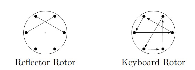
Figure 8. Diagrams of sample reflector and keyboard rotors.
To make a paper Enigma, set the reflector rotor into the “Reflector” circle and the keyboard rotor into the “Keyboard” circle in the paper Enigma available here. It will help to pin the rotors down through the hole in the center. As a check to make sure you are ready to follow along with the examples below, your initial setup should look something like that shown in Figure 9 below (the dashed line has no significance and is only there to make the process easier to follow).
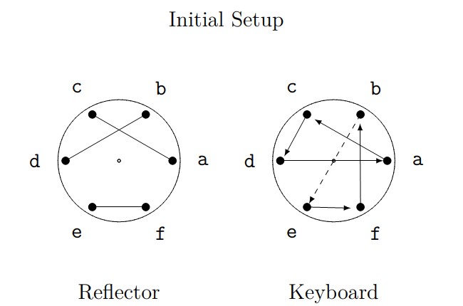
Figure 9. Initial setup of reflector and keyboard rotors.
In general, a letter will be encrypted by sending it through the keyboard rotor; then the reflector; and then “backwards” through the keyboard rotor.
For example, if we pressed \(a\), then:
- The keyboard rotor would send \(a\) to \(c\),
- The reflector rotor would send \(c\) to \(a\),
- The keyboard rotor would send \(a\) backwards to \(d\).
Thus this setup would encrypt \(a\) as \(d\).
Used this way, Enigma would have been a simple substitution cipher and would have been trivial to break. So the actual Enigma machine incorporated one more feature that vastly compounded the difficulty: every time a key was pressed, the keyboard rotor would advance one place.[2]
As an example, let’s encrypt the word \(cab\). When we press the first letter \(c\), the keyboard rotor will advance one place, which we’ll take to be a counterclockwise rotation. Thus the encryption of the first letter would use the setup shown in Figure 10.
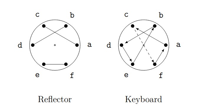
Figure 10. Setup for encryption of first letter.
To encrypt the first letter (\(c\)), we’ll send it through the keyboard rotor, the reflector, then “backwards” through the keyboard rotor:
- The keyboard rotor sends \(c\) to \(f\),
- The reflector rotor sends \(f\) to \(e\),
- The keyboard rotor sends \(e\) backwards to \(d\).
So \(c\) is encrypted as \(d\).
Now for the second letter (\(a\)). Again, pressing the key advances the keyboard rotor one place, so the encryption will be based on the configuration in Figure 11.
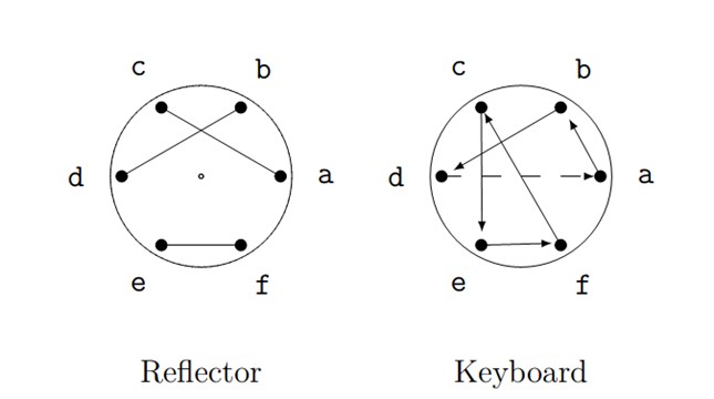
Figure 11. Setup for encryption of second letter.
To encrypt the second letter of our message (\(a\)):
- The keyboard rotor sends \(a\) to \(b\),
- The reflector sends \(b\) to \(d\),
- The keyboard rotor sends \(d\) backwards to \(b\).
So \(a\) is encrypted as \(b\).
Finally, for the third letter, our rotor shifts one place, as shown in Figure 12.
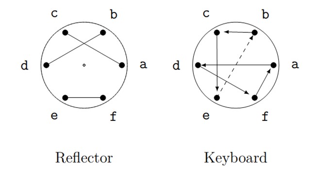
Figure 12. Setup for encryption of third letter.
Our encrpytion of \(b\) will be:
- The keyboard sends \(b\) to \(c\),
- The reflector sends \(c\) to \(a\),
- The keyboard sends \(a\) backwards to \(f\).
So \(b\) would be encrypted as \(f\). Thus the word \(cab\) would be encrypted as \(dbf\).
To explore the basics of rotor design and permutations further, continue to the Activities for Part 1.2 (Encryption).
Return to the overview of Part 1 (Enigma on Paper).
Skip to the overview of Part 2 (The Algebra of Enigma).
[2] The second and third rotors on the actual Enigma would also advance one place for every full turn of the preceding rotor.
Jeff Suzuki (Brooklyn College), "The Theorem that Won the War: Part 1.2 – The Enigma Encryption," Convergence (October 2023)