- About MAA
- Membership
- MAA Publications
- Periodicals
- Blogs
- MAA Book Series
- MAA Press (an imprint of the AMS)
- MAA Notes
- MAA Reviews
- Mathematical Communication
- Information for Libraries
- Author Resources
- Advertise with MAA
- Meetings
- Competitions
- Programs
- Communities
- MAA Sections
- SIGMAA
- MAA Connect
- Students
- MAA Awards
- Awards Booklets
- Writing Awards
- Teaching Awards
- Service Awards
- Research Awards
- Lecture Awards
- Putnam Competition Individual and Team Winners
- D. E. Shaw Group AMC 8 Awards & Certificates
- Maryam Mirzakhani AMC 10 A Awards & Certificates
- Two Sigma AMC 10 B Awards & Certificates
- Jane Street AMC 12 A Awards & Certificates
- Akamai AMC 12 B Awards & Certificates
- High School Teachers
- News
You are here
Modeling the Mirascope Using Dynamic Technology - Additional Figures
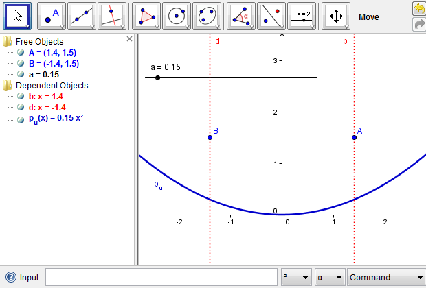
Figure 4c: Two light rays that are parallel to the \(y\)-axis reach an upward parabola.
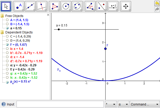
Figure 4d: Hide the intermediate steps to reduce the construction complexity.
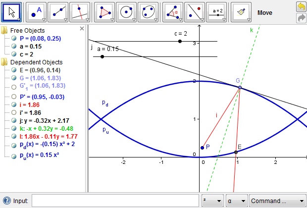
Figure 6a: A light ray from point \(P\) reaches the upper parabola and is reflected to the lower one.
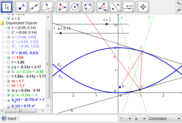
Figure 6b: A light ray from point \(P\) is reflected out of the mirascope.
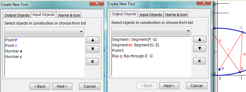
Figure 6d: Defining a new tool to reflect light from point \(P\) out of the mirascope. In GeoGebra, click "Tools" in the menu, select "Create New Tool," and follow the onscreen directions to click the objects involved. In our case, inputs include point \(P\), point \(G\), number \(a\), and number \(c\). Outputs may include all the objects related to the light reflection or, if so desired, the light ray \(q\) only.
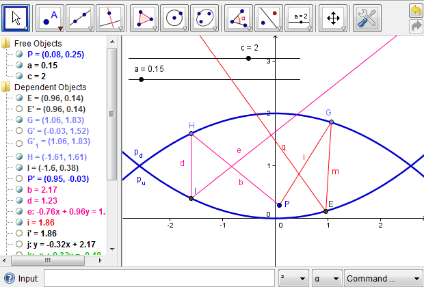
Figure 6e: Using the newly defined tool to reflect a second light ray from point \(P\) out of the mirascope. In GeoGebra, place point \(H\) anywhere on the downward parabola. Point \(H\) is the location where a second ray from point \(P\) touches on that parabola. Next, click the button for the new tool at the upper-right corner. For inputs, click point \(P\) and point \(H\). When prompted for numbers, type "a" and "c". The color of the second ray is changed to distinguish it from the first one.
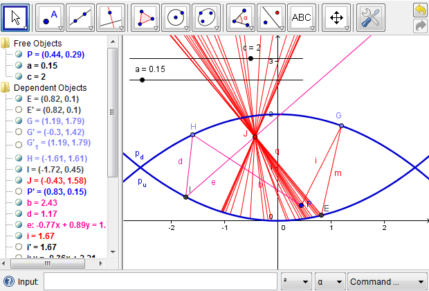
Figure 7c: Modeling more light rays from point \(P\) is not necessary to locate the image of \(P\).
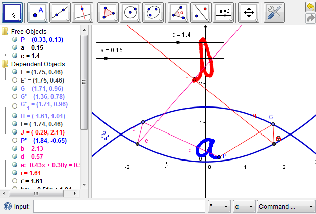
Figure 7d: The image is well above the mirascope if the two parabolas are relatively close to each other.
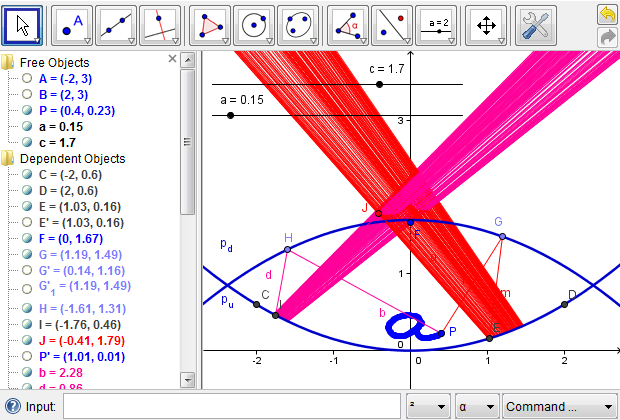
Figure 7e: Finding the appropriate opening by tracing the outgoing light rays.
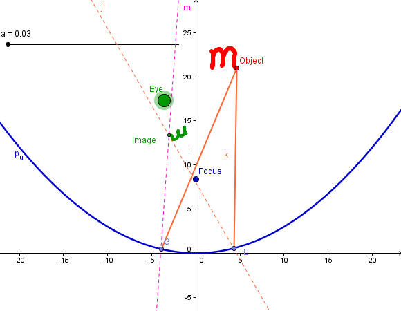
Figure 9: When the eye, the object, and the focus of a parabolic mirror are aligned in certain ways, one may be able to see a clear image with changes in its size and orientation.
Lingguo Bu (Southern Illinois University Carbondale), "Modeling the Mirascope Using Dynamic Technology - Additional Figures," Convergence (May 2011), DOI:10.4169/loci003595